Workshops
MARRS Online Workshop 2021 - January Workshop Information
Topics
- Resolving ZOOM Connection
- Pre-Test
- Website Resources
- Workshop Overview
- Rover Demo
Presenters
- JSU: Dr. Mehri Fadavi
- JSU: Dr. Teresa Demeritte
- ODU: Dr. Walter Deal
- ONU: Dr. Feng Jao
- ODU: Dr. Steve Hsiung
Locations:
Zoom: Host Room
Topics
- 3D Applications
- 3D Printing Overview
- 3D Printing Demo
- Why 3D Printing
Presenters
- ODU: Dr. Walter Deal
- ONU: Dr. Feng Jao
- ODU: Dr. Steve Hsiung
Locations:
Zoom: Host Room

Topics
- Break - Please log out and log into Zoom again at 9:55AM
Topics
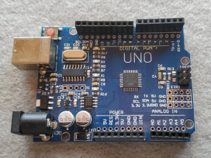
- Defining Arduino and Mechatronics
- Making STEM Connections
- Q & A
Presenters
- ODU: Dr. Walter Deal
- ONU: Dr. Feng Jao
- ODU: Dr. Steve Hsiung
Locations:
Zoom: Host Room
Topics
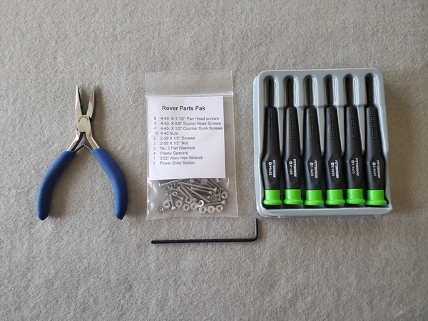
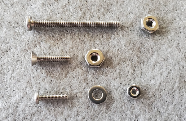
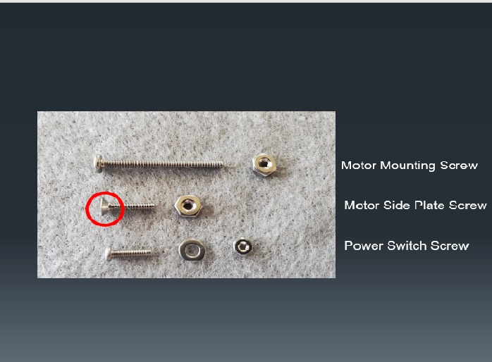
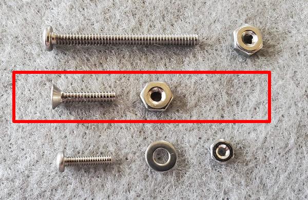
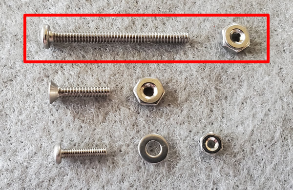
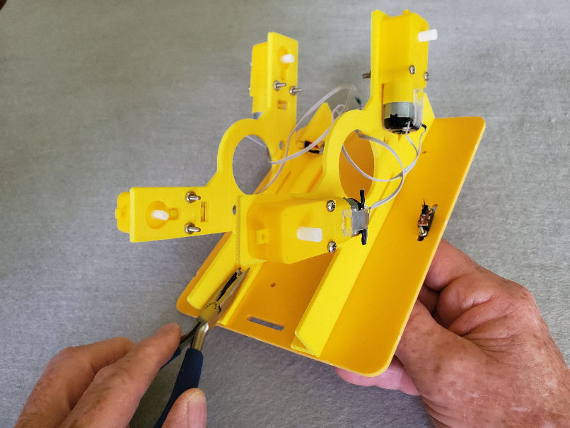
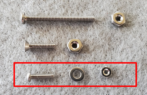
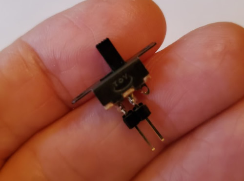
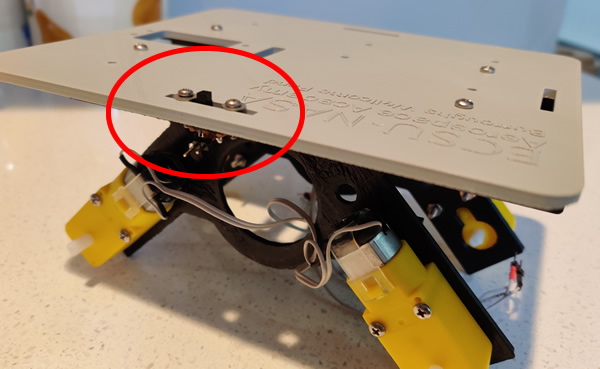
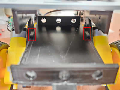
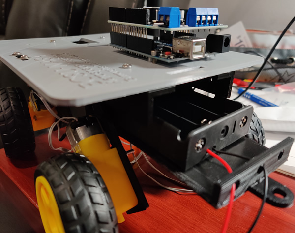
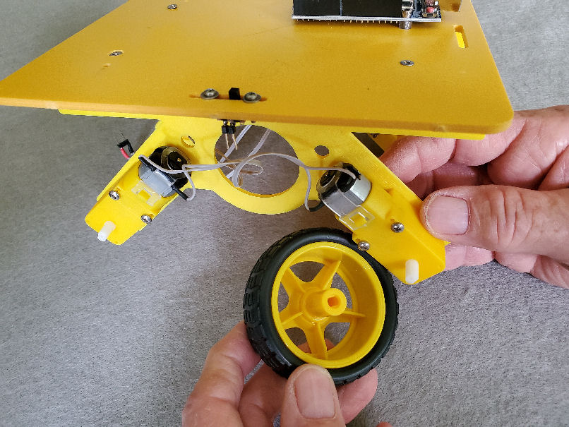
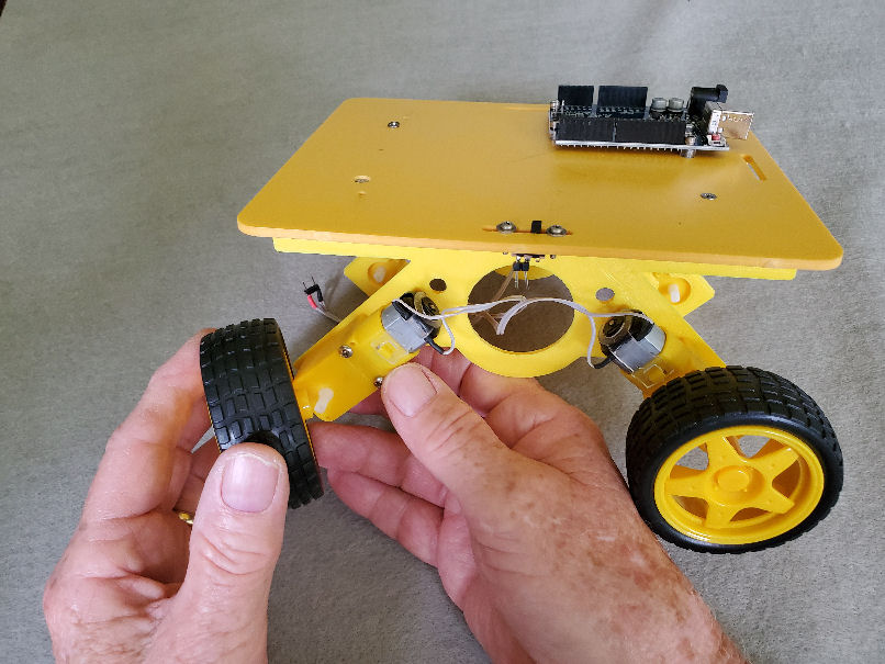
- Check Rover parts
- Overview of Rover assembly
Presenters
- ODU: Dr. Walter Deal
- ONU: Dr. Feng Jao
- ODU: Dr. Steve Hsiung
Locations:
Zoom: Host Room
Topics
- Lunch Break - Please log out and log into Zoom again at 12:55pm
Topics
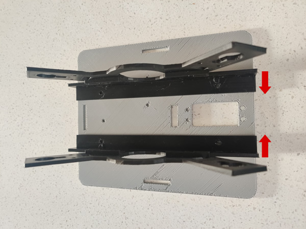
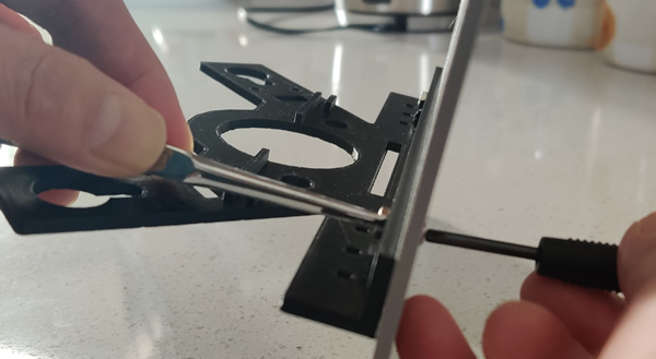
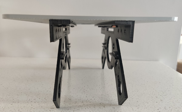
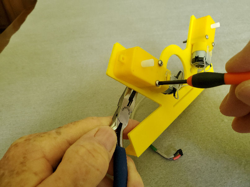
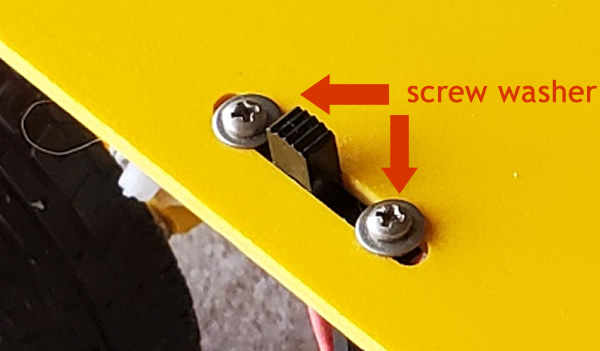
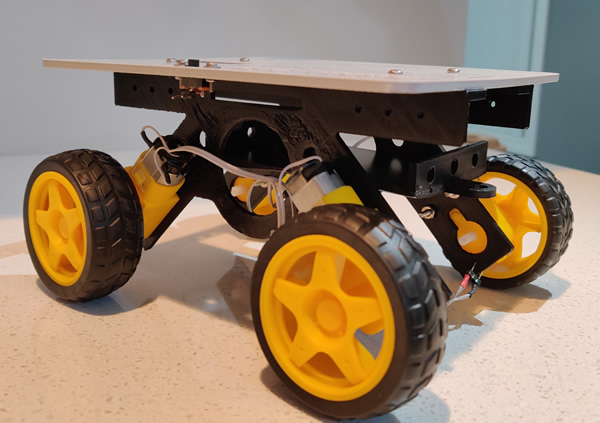
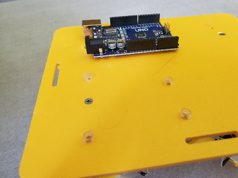
- Rover Assembly
Presenters
- ODU: Dr. Walter Deal
- ONU: Dr. Feng Jao
- ODU: Dr. Steve Hsiung
Locations:
Zoom: Host Room and Breakout Rooms: Walt & Fenny

Topics
- Programming Arduino
- using Arduino to control devices and DC Motors
Presenters
- ODU: Dr. Walter Deal
- ONU: Dr. Feng Jao
- ODU: Dr. Steve Hsiung
Locations:
Zoom: Host Room and Breakout Rooms: Walt & Fenny
Resources:
- Download Arduino IDE (right click on the link and save the file to your computer system)
- Installation of the Arduino IDE
- Arduino ino files
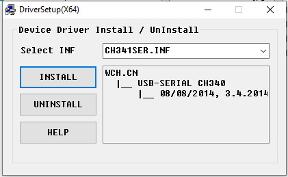
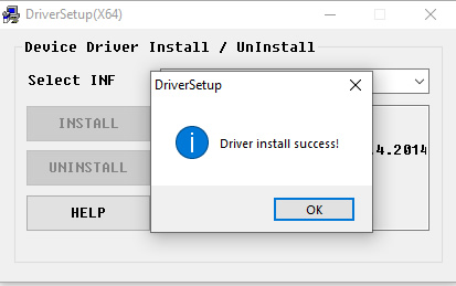
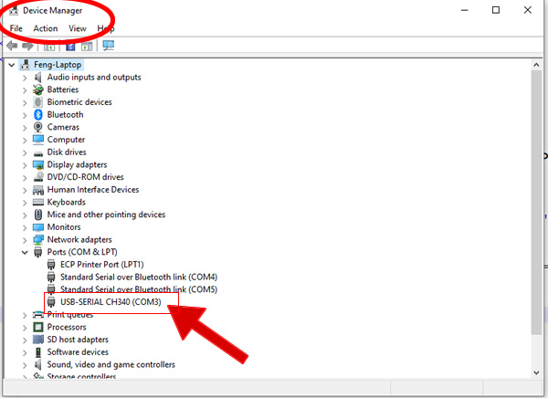
- Arduino driver update
Topics
- Break - Please log out and log into Zoom again at 2:55PM
Topics
- Arduino programming
- Using Bluetooth for remote control
- Review and Testing Rover control and Navigation
Presenters
- ODU: Dr. Walter Deal
- ONU: Dr. Feng Jao
- ODU: Dr. Steve Hsiung
Locations:
Zoom: Host Room and Breakout Rooms: Walt & Fenny
Topics
- Rover Operation and Demonstration
- Q & A
Presenters
- JSU: Dr. Mehri Fadavi
- JSU: Dr. Teresa Demeritte
- ODU: Dr. Walter Deal
- ONU: Dr. Feng Jao
- ODU: Dr. Steve Hsiung
Locations:
Zoom: Host Room