About UcDistance Training
Hardware REV 3 Training System
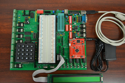
The Rev3 Training System is a direct revision from the Rev2, where the TI/Tiva C Series LaunchPad is included to be used with all the available peripheral devices on the trainer board such as SPI, I2C, LEDs, LCD, Keypad, EEPROM, DAC, 2.4GHz transceiver, isolated stepper/DC motor driver, etc. This trainer can work with PIC, Arduino, and ARM M4 microcontrollers.
PIC REV 2 Trainer Board
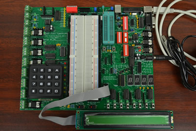
PIC REV 2 Trainer Board
The Rev2 has additional features from Rev1, which has the following:
- The system could be used with Microchip (PICKit2, PICKit3)7, NXP/Philips (LPCX), PIC_Trainer_Rev2and Ardunio systems for programming, simulation operation, and debugging.
- Power options include +-5V, +-12V, +3.3V, digital and analog I/Os, LCD, and LED displays, RS232 and USB communication capabilities, 2.4GHz wireless module, and high and low power isolation for digital/analog and motor drive controls.
- OPAmp, EEPROM, DAC operations, and SPI Bus are accessible.
- FET/IRF530*8 power for stepper and DC motor controls are available.
PIC REV 1-2 Trainer Board
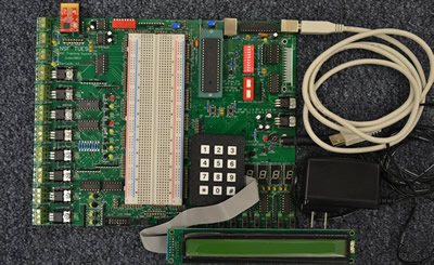
Hardware: There many elements such as LED drivers, DIP switch inputs, 7 segment connections & drivers, Max232 configurations, DAC connection, EEPROM connections, 2.4 GHZ MRF24J40MA RF module, SPI interface, LCD connections, 3*4 keypad pins pull up, DB25 Parallel port I/O buffered interface connections, optical isolator connections, power FET configurations, and 8 bit SPDT hardware switch debounce are already done on the PCB (Printed Circuit Board). Users are only required to use proper interface between the PIC microcontroller pins and available modules on board to do the desired experimentations. The hardware operations and pin description is detailed in the “Hardware Operation” section.
Software: There are two kinds of software that can run on this training system. The “PICKIT2” that is downloadable from www.microchip.com/pickit2 runs on a PC USB port and its operations are detailed in the first part “Software Operation” section.The other software is “ICPROG” that is downloadable from www.ic-prog.com/index1.htm runs on a PC DB25 parallel port. The operation is also introduced in the second part of “Software Operation” section.
New Features in Rev3
- The TI/Tiva C Series LaunchPad ARM M4 module interface is included that can be used with all the available peripheral devices on the trainer board such as SPI, I2C, LEDs, LCD, Keypad, EEPROM, DAC, 2.4GHz transceiver, isolated stepper/DC motor driver, etc.
- I2C interface via TCN75A temperature sensor
- The 7-Segment interface is eliminated in Rev3
- The GS Encoder via EVEGA2 is eliminated in Rev3
The Rev2 has the following features:
- The system could be used with Microchip (PICKit2, PICKit3), NXP/Philips (LPCX), and Arduino systems for programming, simulation operation, and debugging.
- Power options include +-5V, +-12V, +3.3V, digital and analog I/Os, LCD, and LED displays, RS232 and USB communication capabilities, 2.4GHz wireless module, and high and low power isolation for digital/analog and motor drive controls.
- OPAmp, EEPROM, DAC operations, and SPI Bus are accessible.
- FET/IRF530*8 power for stepper and DC motor controls are available.
Operation Selection:
- DIP S1: 1-8 for different PIC MCU package selections
- DIP S2: 1-2 for different PIC MCU operation selections
- DIP S4: 1-8 for PICkit2 or PICkit3 Selections
- DIP S6: 1-8 for PIC or LPCX operation selections
- PICkit3 programmer module interface
- Open VPP, DATA, & CLK programming interface for universal programming on any PIC microcontroller
- Automatic isolation switches for PICkit2, PICkit3, and LPCX
- NXP, LPCXpresso module interface for ARM M0 32 bit microcontroller core: LPC1114FN28
Modulus Part/Port:
- Dual OPAmps via MCP6024
- GS encoder via EVEGA2 and interface
- 64K EEPROM via 25LC256
- 12 Bit DAC via MCP4822
- 2.4GHz RF transceiver communication module: MRF24J40MA
- 4*4 or 3*4 matrix interface
- 40*2 or 20*2 LCD module interface
- DB9 RS232 serial port and two channels TTL-RS232 interface
- 40 Pin ZIF socket for different DIP MCU interface and applications
- 2 Potentiometers for ADC interface and applications
- All the interface are done with pre-made jumper wires between X connectors that are female socket housing connectors
Power Selection:
- Power jumper selection of +5V or +3.3V
- Jumper selection of -5V or -12V power source for application and project
- Positive and Negative power source test posts
- Positive and Negative power source interfaces
Power FETs: Up to 2A on the trainer board and 15A if made on external interface
- All digital control signals are isolated from the high power FES via 8 optical isolators to the power FETs via IRF530 or IEF540 with indicators: LEDs: 15-21
- 2 Bidirectional terminal block connectors with LEDs: 11-14 indicators, used with H- Bridge or other applications.
- 8 terminal block connections for any high power switch applications: Stepper, DC motors and solenoid controls and applications
- Isolated external high power connector
Digital I/O:
- 8 Input selections via S7: 1-8
- 8 Output indicator selections via LEDs 3-10
- 8 Output indicator or low or high power selections via LEDs 15-21
- 8 SPDTs hardware debounced switch outputs and indicator: LEDs 23-30 for I/O uses and applications
- 2 Snap action SPDT selection via: S8 and S9
- 4 7-Segment Indicator via DIS1-DIS4
Changes Made in PIC Training System Rev 2 from Rev1
- Eliminate DB25 Parallel Port Connector
- Eliminate SV3 14 Pin Expansion Port
- Eliminate DB25 Buffered Inputs: Yellow LEDs 31-34
- Add DB9 RS232 Serial Port and Two Channels TTL-RS232 Interface
- Add Input Indicator Yellow LEDs 31-38
- Add Output LEDs 3-10 with Driver Interface
- Add VDD Power Jumper Selection of +5V or +3.3V
- Add Jumper Selection of -5V or -12V
- Add Negative Power Source of -5V or -12V
- Add Positive and Negative Power Source Test Posts
- Add Open VPP, DATA, & CLK Programming Interface for Universal Programming on Any PIC Microcontroller
- Add PICkit3 Programmer Module Interface
- Add NXP, LPCXpresso Module Interface for ARM M0 32 Bit Microcontroller Core: LPC1114FN28
- Add DIP S5 for PICkit2 or PICkit3 Selection
- Add DIP S6 for LPCX Selection
- Add Automatic Isolation Switches for PICkit2, PICkit3, and LPCX
- Add GS Encoder (EVEGA2) and Interface
- Change all X Connectors Interface Post to Socket Housing Connectors